3905 starlight circle Mayslanding, 08330 NJ
E-mail us: [email protected]

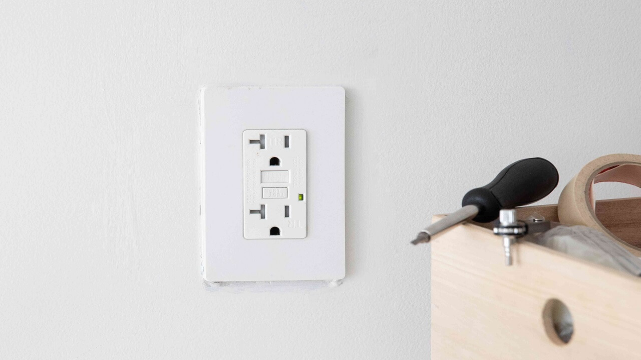
An electrical outlet, as defined by the National Electrical Code (NEC), is commonly referred to as a receptacle and more widely known as a socket outlet according to the International Electrotechnical Commission (IEC). In essence, it serves as the point within an electrical wiring system where current can be accessed and utilized by electrical appliances and equipment through plugging them into it.
An outlet receptacle typically accommodates one or more receptacles or a supply contact device, facilitating the connection of electrical loads via plugs and switches.
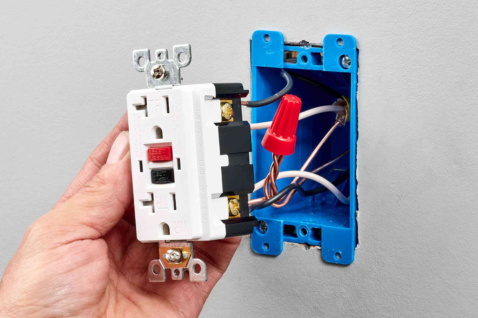
A standard outlet, often termed as an ordinary outlet, features screws (terminals) on both sides. The brass screws are designated for connection to the line (hot, live, or phase) wire, while the silver screws are intended for connection to the neutral wire. In practical terms, the hot wire originating from the main breaker is connected to the narrow blade terminal, while the neutral wire is connected to the wide blade terminal. The ground wire, usually identified by its green color, is connected to the ground terminal.
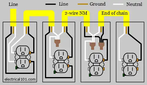
Below is a series of electrical outlet wiring diagrams employing NM cable and four outlets. Also provided are illustrations of a 240-volt dryer outlet and a grounding diagram.
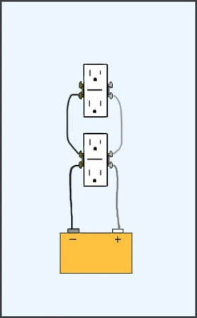
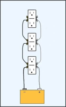
In the first diagram, a 2-wire NM cable delivers line voltage from the electrical panel to the initial outlet box. The black wire (representing line) and the white wire (for neutral) connect to the outlet terminals. Another 2-wire NM cable extends to the subsequent outlet, and this pattern continues until the end of the chain.
It’s important to note that while the diagrams presented here are simplified for clarity, actual electrical outlet boxes can involve multiple NM cables entering and exiting. For a more detailed depiction, refer to the Actual Switch Box Wiring Diagram.
In the diagram below, a 3-wire 10 AWG NM cable is utilized to supply 240 volts from the electrical panel to the dryer outlet box. The black wire, designated as line “A” phase, and the red wire, representing line “B” phase, both deliver the 240 volts. Meanwhile, the white wire serves to supply neutral to the dryer outlet.
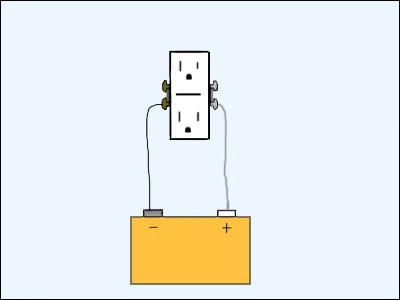
Additionally, the grounding connection is depicted in this diagram to ensure proper safety measures are followed.
In each outlet box, all ground wires are interconnected, ensuring they are securely joined together. Furthermore, the ground is appropriately linked to the ground terminal of any device present in the box, whether it’s a switch, outlet, light fixture, or any other electrical component. This connection helps maintain safety standards and ensures proper grounding throughout the electrical system.
Simple One Single Outlet
Wiring Two Outlets (Double Outlets)
Wiring Three Outlets (Triple Outlets)
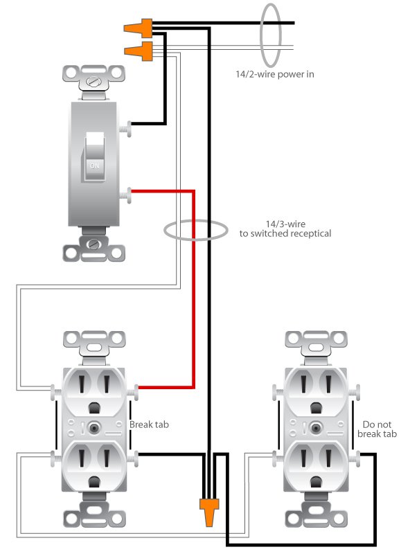
Wiring A Switched Outlet Wiring Diagram